Old wheeled tug. Rubber model of a paddle steamer
Continuing the theme of old wheeled ships, I want to show you another ship I found. It would be more accurate to say that it was not found by me, but rather discovered for myself, and now for you, if you have not seen it yet. The first time I noticed it was last year, when on a sunny February day we made an outing to the village of Rozhdestveno. That time we did not approach and examine it, and the purpose of the walk was rather to see the village. But the ship has sunk into our souls since then, and now, a year later, the Volga ice is under our feet again, and driven by the wind we are again walking along the Volga towards the old paddle steamer, which is like a magnet attracting.
In general, walks on the Volga ice always give a lot of impressions. On a sunny weekend there are a lot of people walking here, and this is not surprising. After all, from here an excellent panoramic view of the city opens up, here you can catch your breath from the city smog, and standing somewhere in the middle, it’s worth imagining that such a colossal mass of water is moving under this 35-centimeter crust, and either from the realization of this, or from the freezing wind that has rushed across a cold chill runs through the body. But during these walks you seem to be charged with some kind of energy, as if drawing it from a river.
So admiring the winter landscapes, we passed through the Volga and the island. Here, on the banks of the Volozhka, 3.5 kilometers from Samara, on the territory of the tourist center, is the same old steamship that was the goal of our walk.

This ship is located on the territory of the TTU tourist center; a watchman’s house has been built on the deck, which is why it has not yet been sawed up and demolished to a scrap metal collection point. Several bridges lead to the ship; apparently, it is used for economic purposes.

An old steam tug, the brainchild of the Krasnoye Sormovo plant. In the early 30s of the last century, this plant produced a series of tugs with a capacity of 1,200 horsepower. At that time these were the most powerful serial tugs on the Volga. The first series of such tugs were: “Red Miner”, “Industrialization” and “Collectivization”. They were intended for driving oil barges with a carrying capacity of 8 and 12 thousand tons along the Volga. Only the “Stepan Razin”, the former “Rededya, Prince of Kosogsky”, which was built before the revolution in 1889 and had a power of 1600 horsepower, surpassed them in power. These tugs ran on fuel oil, were equipped with an inclined steam engine with two boilers and superheaters, the total heating surface of the boilers was 400 m2. The use of superheated steam made it possible to significantly increase the efficiency of the steam plant. A steam installation with three-stage water heating, that is, water was supplied to the boilers through heaters that received heat from the already exhausted steam. The ship had an electric lighting network, the electricity for which was generated by a 14 kW steam dynamo, providing a direct current of 115 V. To lift anchors from the ground, the ships were equipped with a steam windlass at the bow of the ship and a stern capstan. In addition, they had a horizontal steering machine. For the first time on river fleet A steam towing winch was installed, on the drum of which almost half a kilometer of strong steel cable was laid. The machine and boilers, like all the ship's equipment, were designed and manufactured at the Krasnoye Sormovo plant.

The hull of the ships of the first series was riveted and was divided by nine bulkheads into ten compartments: in the first, bow compartment there is a pantry and a box with anchor chains; in the second there are cabins for sailors; the third is a rubber dam, which serves to prevent the penetration of gases from the fuel compartment; in the fourth there is a tank with fuel oil; the fifth was the engine room; in the sixth boiler room; in the seventh there is an aft fuel tank, then again a cofferdam, behind which are the cabins of oilers and stokers, and the aft compartment, where the stern anchor chains and machine parts were located. In the casing rooms, which are located on the outskirts next to the paddle wheel arch, there are cabins: two pilots, an engineer and two assistants, a spare cabin, a red corner, a dining room, a laundry room, and a bathroom. The kitchen and dryer are placed in front of the boiler casing.

The forward deck house houses the cabins of the commander, his assistant, one pilot, and one radio control room. On the left side you can see inscriptions on the doors of the captain and the radio room.

The paddle wheels have been dismantled, so I’ll just show their diagram. The wheels had a diameter of 4.8 meters; each wheel had 8 metal plates - blades. To reduce energy losses when entering and exiting the slabs from the water, they are made rotating, due to a hinged connection with an eccentric mechanism that regulates the position of the slabs when the wheel is turned.
This wheel design has greater efficiency, ensuring that the blades enter the water at large angles of attack. The performance qualities of the new tugboats were significantly higher than those of pre-revolutionary vessels of similar power.
But along with all these technical advantages, the new tug had a number of significant shortcomings, which were identified after the “Red Shakhtar” tug was put into operation. Then the customer, which was the People's Commissariat water transport, claims were made against the plant. For example, when moving with a load, the ship did not obey the rudder well. It was found that the poor handling and longitudinal instability of the vessel was a consequence of an incorrectly designed hull, it was too narrow, the towing hook was too high, and the wheels were too offset towards the bow of the vessel. On the tugboats of the next series, these defects were eliminated, but on the already released ships “Industrialization” and “Collectivization” the changes were partially affected and the shortcomings regarding the hull design remained.
By 1936, the plant built a series of tugs of the Tsiolkovsky type according to the same project, with some changes relating, in particular, to the hull of the vessel.
Drawing by Mikhail Petrovsky taken from the website of the magazine Tekhnika Molodezhi
An interesting article about them was published in the 8th issue of the magazine Tekhnika Molodezhi for 1982, from where I learned a lot useful information about the ship.
Through the snowdrifts, having filled my boots with a fair amount of snow, I walked close to the ship. Here there is no snow at all under the rampart, and the height of the side allows you to move freely without hitting your head on the support brackets, of which there are many. The arch of the paddle wheel is closed; instead of a shaft, a channel is installed, which serves as a support for the decking, which just covers it. But you can carefully examine the structure of the body.
This design of the body kit, namely support on triangular brackets resting on the hull, was used on the first three ships: “Red Miner”, “Industrialization” and “Collectivization” and created some problems. The fact is that the water thrown by the wheel hit the brackets, thereby creating additional resistance to movement. On the vessels of the next series, the design of the outrigger supports was changed. The brackets began to be made in the form of beams suspended from vertical posts installed on the deck, and the ship's hull was made entirely welded; these changes made it possible to reduce the water resistance experienced when the ship moves.
This means that this tug is one of the first trinity of 1200 strong.
Having examined the hull, it turned out that it was welded, but with noticeable traces of alteration; the portholes were previously located lower on board; you can see their welded openings and were moved higher relative to the waterline.

It should be noted that the 30s were restoration years for shipbuilding, the industry lacked qualified personnel, and there were no research developments. On the river, pre-revolutionary vessels were mainly used; they were often converted for new tasks.

In terms of overall hull dimensions, the steamer is also very similar to the first series of tugs. Thus, the lead steamship of the first series, “Red Miner,” had dimensions of 65 x 9.8 x 3.2 m, which coincides with the dimensions of our oil tanker, the dimensions of which were measured, very approximately, on a map. However, they are the same. By the way, the width is given without taking into account the run-ins, along the waterline.

I climbed onto the deck, but did not approach the guardhouse, somehow I didn’t want to get caught by the watchman, I don’t think that my interest in the ship would have aroused his approval. Perhaps there are storage facilities here, and here I am without an invitation. Although I really wanted to see it, I didn’t get impudent; maybe I’ll come back here in the summer, when the tourist center is open and I can pass for a vacationer.

I walked around the ship, and the markings of the ship's draft scale were still visible on the rusting hull.


Looking through the forums of lovers of such river antiquities, I often came across the opinion that this is the tugboat “Industrialization”; there are very strong similarities with its surviving photographs, and the dimensions, the design of the outrigger supports, the number of windows on the deck superstructure - all this only confirms that this is definitely one of the first 1200 strong Sormovo paddle steamers.

One fact confused me. On the arch of the left paddle wheel, the one located on the side of the camp site, the numbers “1918” and the letters at the top of the arc, either “rn” or “ra”, are barely visible. Paint stains, its layers showing through one another and the ongoing corrosion make it difficult to make out the full name of the ship. I tried to search for ships with a combination of these letters and numbers on the Internet, unfortunately, the search did not give any results.

Perhaps it was renamed, but this is only an assumption, because I have never come across any mention of renaming tugboats from the first three, except for the first-born. Only “Red Shakhtar” was renamed “Georgiy Dimitrov”.
Near the axle support propeller shaft the porthole was open. With the hope of seeing at least some preserved part of the steam engine, I looked inside. Pitch darkness, only the luminous circles of portholes on the opposite side were visible, through which light passed and immediately dissolved in the darkness. Having raised the iso fairly high, I stuck my hand with the camera inside and took a few shots.

If you look closely, you will notice that the connection of the structural elements inside the body remains riveted.

Then I turned on the flash and clicked a few more times. There was a noise somewhere nearby. I listened, everything became quiet. But he didn’t put the camera in the porthole anymore. Walking along the hull of the ship, I again heard a creak coming from inside. Yeah, that means I didn’t go unnoticed and attracted someone’s attention. However, no one came out. Oh well, hopefully I'll be back next time the snow melts.

As I was leaving, I looked back to take another look at this river rarity, worthy of becoming museum exhibit river fleet.


Czech magazine "ABC" The topic brought to the attention of ship modellers today, it seems, will be of interest to copyists of various levels, from schoolchildren building contour rubber-engined “straightforward” ships, to experienced sportsmen-radio operators. The fact is that we offer a steamship with paddle wheels for reproduction in miniature - model shipbuilders do not need to be told in detail about the “delicacy” of such work.
One of the most elegant river steamships of the last century, the Czech-built Bohemia, created in 1841, was chosen as a prototype for copying. Along with its spectacular appearance, this ship is also characterized by comparative simplicity, which in no way comes to the detriment of the copy version of the model.
A copy of “Bohemia” can be made not only for use in various sports classes, but also in different designs. For example, a fairly large elongation hull with different contours of the bow, central and stern parts is well reproduced both in the classic version with frames and plating made of precisely fitted linden or balsa slats, and in the shell version, made of fiberglass on a blank. It would not be a sin to remember such an option as making an entire body from a single block of wood, followed by hollowing it out until a wall thickness of 2-3 mm is obtained, followed by installing sparsely spaced frames. Despite the exaggeration of such technology, which is more typical for school ship models, when copying the “Bohemia” with its wide, low hull, such a technique is quite justified, even in the case of creating a high-quality model.
Having determined the copying scale, it is necessary to draw the main projections of the model in full size and arrange the “filling” of the body. To help those who are thinking about making a similar micro-steamer, we present the layout of the most complex option - a model with a length of only 720 mm, with radio control. As can be seen in the figures, even with such small dimensions, all nodes are placed in the case quite freely, so when creating a larger copy, there should be no problems at all.
At this scale, it is easiest to make the deck entirely removable by gluing a blank for it from individual pine or linden slats with a cross-section of 2x4 mm. The model's drive - from a conventional unboosted electric motor with a voltage of 3-4.5 V - is quite sufficient in power for large-scale travel speeds. Unlike the prototype, it is better to place the gear reducer inside the housing. It should have a gear ratio of about 1:10. The single shaft of the paddle wheels is made of steel wire with a diameter of 4 mm and on the copy passes through two bronze bearings installed in the side bosses directly below the deck.
The materials for making the paddle wheels themselves can be very different. Let's name only two main options: all-wood, using plywood “rims”, slats and plates, and all-metal. In the latter case, in addition to steel or brass wire, you will need to find suitable sheet blanks for rowing plates. In the same way, different designs are acceptable when working on the steering wheel and its drive.
Superstructures and all components located on the deck are best mounted tightly. The main material for volumetric superstructures must be celluloid, although “boxes” made of plywood, textolite or even cardboard will turn out not much worse (the latter will have to be soaked through with warm drying oil). Fences and awning posts are made of wire and assembled by soldering. For small parts, the easiest work and best appearance will be ensured by using solid wood. The final external effect will depend on the quality of finishing, varnishing and painting. The body in the hollowed-out version is impregnated with drying oil or liquid two-component parquet varnish, after which it is painted.
The driving performance of the miniature “Bohemia” is very good. True, it must be admitted that for such a copy it is still better to have a water surface with a small wave. After the start, the model quickly accelerates and, despite the large elongation of the body, responds quite “briskly” to steering wheel deviations. At the specified copying scale, the weight of a fully equipped model should be in the range of 1000-1100g.
DESCRIPTION OF THE STEAMER “BOHEMIA”
The ship's hull is divided by bulkheads into the following compartments (starting from the bow): open bow compartment 5.35 m long, galley - 1.5 m, second class saloon - 6.3 m, crew cabins and storage rooms - 3.3 m, engine room compartment and boiler room - 5.85 m, crew cabins - 1.5 m, ladies' room (cabin) - 3.6 m, passenger compartment first class - about 10.6 m. Toilets were located in superstructures located directly in front of the paddle wheel housings. The deck was used for passengers to walk around; if necessary, benches were installed on it. The rear part of the deck could be covered with a canvas awning stretched over the side posts.
The steamship's hull, superstructure and paddle wheel casings are made of wood: only the side and bottom frames were made from iron corner profiles. As can be seen from the above figures, “Bohemia” had an unusually elongated hull with an almost rectangular cross-section in its central part and rounded contours in the bow and stern. The complete displacement coefficient is 0.65. The front of the keel curved elegantly upward, forming at the end a base for mounting the figurehead - a silver-painted Bohemian lion with a gold royal crown on its head. The total length of the bow figure was approximately 0.9 m. The aft part of the hull was steep. She carried a 1.6 m long rudder plate suspended on three hinges.
“Bohemia” was equipped with a two-cylinder steam engine with oscillating-type cylinders, vertically arranged. The diameter of the cylinders was 0.525 m and the stroke was 0.725 m. At 40 rpm, the engine developed a power of 37.5 kW (51 hp). The steam engine was supplied a steam condenser and a stroke reversal system. It was made in England and was very advanced for its time. It is interesting that this machine was after “Bohemia”. long time served on another ship, and there are assumptions that she works to this day on the ship “Dizbar”.
The steam boiler was manufactured by the same company that built the steam engine. The operating steam pressure is 1.33 atm. Inside the boiler with three fireboxes with a combustion area of about 35 m2, 165 copper tubes with a diameter of 54 mm, connected in three bundles, were placed. The fuel combustion products passed between these tubes, heated the water and were released into the atmosphere through a chimney about 4.5 m high. The design of the pipe was an assembly of five sections, and between the second and third there was a connector that allowed the upper part to be tilted (folded) when passing under low bridges. The system for lowering and raising the pipe is a pulley system, using blocks and ropes leading to a folding mast.
The steam engine rotated the side paddle wheels through a gear transmission with a gear ratio of 1:1.5, and the drive gears were located outside the housing in the volumes of the paddle wheel casings. The iron rims of the paddle wheels had an outer diameter of about 4.1 m and the lower edge was equal to the level of the bottom point of the hull bottom. 12 propeller blades on each wheel were screwed to the metal spokes; their size was 0.35 x 1.6 m. The casing with an outer diameter of 2.15 m and a width of 1.95 m had waterproof walls, except for the outer ones, which were wooden gratings.
The wooden steering wheel was operated by cables running from the steering wheel through a pulley system. On the axis of the wheel, the diameter of which was 1.5 m, there was a drive drum with a cable. A special platform was equipped for the helmsman, which allowed him to have a forward view of the water area.
The Admiralty type anchor, about 1.2 m long, was raised manually and, in the stowed position, lay freely on the starboard side of the front part of the hull.
To carry the flag and place the mechanism for folding the chimney, a large mast 9 m high was installed in the front part of the steamer. It also folded back, for which two cables running from the mast forward and to the left side served. To carry the stern flag, a rigid flagpole with a height of 3.3 m was installed at the rear of the hull.
The rear passenger compartment (first class) was illuminated by five portholes on each side, the front (second class) by two pairs of portholes. Each of them was a three-section opening with glass with a total size of 0.6x1.8 m. Two windows were located on the front wall of the building to brighten the galley; skylights were installed above the engine room and crew quarters. The captain's bridge with rigid handrails was mounted between the casings of the paddle wheels - a ladder led to it from the deck. Ahead of the deck was a conductor's bench, in front of which a bell was suspended on a curved bracket. There, nearby, there was a chimney from the galley and a steam exhaust pipe from the boiler safety valve.
The side plating of the hull was protected by four overhead strips. The lowest one was located almost above the waterline; the next one ran along the lower edge of the portholes, and along their upper edge was another bar. The fourth and last one walked along the edge of the deck.
During passages through Czech territory, a red flag with narrow white horizontal edges and a silver Czech lion in the middle was raised on the stern flagpole. On the territory of Hungary, the flag was replaced by a red-white-red one with the image of a shield. The mast carried a long white-red-white pennant with the name of the ship in white inscription. On the inner walls of the paddle wheel casings there was a small Hungarian emblem (a double-headed eagle with a shield).
The bottom of the hull and the lower part of the port, including the lower trim strips, were dark brown. The strip between the portholes, porthole frames, entrance deck railings, paddle wheel casings (excluding grilles), overhangs, fences, mast, flagpole, and skylight housings were painted white. Red: top three rows of trim strips and paddle wheels. The anchor, the upper deck casing of the steam boiler, all the chimneys and parts of the frames visible in the open forward part of the hull were black. The deck, captain's bridge, conductor's bench, steering mechanism with bridge and rudder blade had the color of natural wood impregnated with linseed oil. The paddle wheel grilles and stripes at the top and bottom of the portholes were painted dark green.
The hull of this steamship model is a flat plank with a streamlined shape. The front end has a traditional point for ships and boats, which reduces water resistance when moving forward, and the aft part of the hull is simply cut off in the transverse direction. A tin rudder is installed here.
The easiest way to attach it is by cutting it into a pre-made slot in the stern. By bending or bending it, you can send the boat in a circle or change direction. There are two nails driven into the front and rear parts of the hull: these are support pins; the deck is installed on them. There are wide cutouts made on the sides of the steamer's hull for the blade propulsion.
Propulsion model of a paddle steamer
It is installed on two flat sheet metal brackets attached to the cutouts. The propulsion unit consists of two wheels with blades and an axle. The wheel hubs are two wooden rounds (or plugs), along the circumference of which slots are cut for tin blades. The wheels are protected by tin arches attached to the cutouts of the body.
To drive the wheels into rotation, a rubber motor is mounted on the body. For it, pulleys (rollers) are installed along the center line of the body in its front and rear parts, through which a thin elastic band is pulled. One end of it is attached to the front part of the body, and the other - to the axis of the blade propulsion.
By rotating the latter, the rubber band is wound around its axis: this is how the rubber motor starts. If you now let go of the wheel, the rubber band will begin to unwind, causing the wheel with blades to rotate through the axle.
Deck of a paddle steamer model
It is hollow to cover all the protruding parts of the body. Cut out of tin. Figure 1 shows a pattern for a steamship deck: the shaded areas of the cut blank are folded back to form the bow and stern parts of the deck.
The deck superstructure itself is installed in the places marked with dotted lines on the pattern. It can also be made of tin; but it’s easier to assemble it from wooden elements: a flat plank platform, a cabin house and two pipes (really from pipes or sections of a round wooden rod). Foam plastic may be suitable as an affordable and convenient material for superstructure elements.
Any pencil can serve as a mast for this steamer, and harsh black threads can serve as guy ropes. The deck is installed on the housing pins intended for it and is additionally supported by its cutouts on the sides on the axis of the blade propulsion.
Painting a paddle steamer model
The wooden blank of the model body is best protected from getting wet by oil paint. It can be applied with a brush in two layers: the first is the most liquid, for better saturation of the wood surface, and the second is of normal consistency, of any color: after all, the hull is practically invisible from under the shell of the deck.
To paint the remaining elements of the steamship model, it is convenient to use aerosol cans, and the paint can be different: the ship will turn out more elegant, more beautiful. Aerosol coating is easier to apply and adheres better to any material - both metal and wood, forming a thin, light paint layer that is not burdensome for a small model.
Each element of the model can be painted separately as it is being manufactured, that is, even before assembly. However, if it is decided to finally paint the model after assembly with one color, the preliminary element-by-element coating of the parts can be omitted and an aerosol can can be used on the finished model.
Launch of a paddle steamer model
Preparation for launching the boat comes down mainly to tightening the rubber motor. To do this, it is not necessary to raise the deck: access to the rubber motor is provided from the outside, through the blade mover. It is enough to take the model in your left hand, and insert your right index finger between the propeller blades and rotate it. Z
You need to spin the propulsion unit in any position of the boat in your hand from its bow - then the rubber motor will spin the blades in the right direction. Then, holding the propeller blades with your left hand, lower the model onto the water so that they are submerged in the water: you can, by adjusting the steering wheel to the desired course, release the boat on its first voyage. Its range will depend on the degree of twist of the rubber motor.
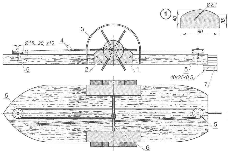
Rice. 1. Model of a paddle steamer: 1-deck; 2-deck superstructure with pipes and deckhouse; 3 - body; 4 - support pin (1x25.4 pcs.); 5 - hub of the blade wheel; 6-blade; 7 - rubber motor (L650); 8 - wheel guard arch; 9 - cutout of the housing for the propulsion unit; 10-steering wheel; 11 - rubber motor pulley (2 pcs.); 12-pin rubber motor retainer (L15); 13 - wheel bracket. A - deck pattern

Rice. 2. Installation diagram of the rubber motor: 1-propeller bracket (2 pcs.); 2-propeller; 3 - propeller guard; 4 - elastic band; 5 - pulleys (rollers); 6 - propulsion axis; 7 - steering wheel
In the soul of every boy there lives a navigator, so any stream of rain is already a river, and a large puddle is a whole sea, calling to launch boats - from the simplest, from a chip or a sheet of paper, to specially planed ones, and even more so combined ones, like those proposed by a German magazine " Technium" self-propelled model of a steamship. Yes, not an ordinary steamship, but an old one, two-pipe, with paddle wheels on the sides. What child wouldn’t want to build one, especially since its design is quite accessible for independent reproduction.
Indeed, all the parts are so simple that they can be made and assembled in one evening. Judge for yourself. The model essentially consists of two large parts: a hull with a propulsion unit and a deck superstructure. Let’s take a closer look at what components they are divided into.
Frame
It is a flat board with a streamlined shape. The front end has a traditional point for ships and boats, which reduces water resistance when moving forward, and the aft part of the hull is simply cut off in the transverse direction. A tin rudder is installed here. The easiest way to attach it is by cutting it into a pre-made slot in the stern. By bending or bending it, you can send the boat in a circle or change direction.
There are two nails driven into the front and rear parts of the hull: these are support pins; the deck is installed on them. There are wide cutouts on the sides of the body for the blade mover.
Mover
It is installed on two flat sheet metal brackets attached in the cutouts. The propulsion unit consists of two wheels with blades and an axle. The wheel hubs are two wooden rounds (or plugs), along the circumference of which slots are cut for tin blades. The wheels are protected by tin arches attached to cutouts in the body.

Rice. 1. Model of a paddle steamer (click to enlarge): 1 - deck; 2-deck superstructure with pipes and deckhouse; 3 - body; 4 - support pin (1x25.4 pcs.); 5 - hub of the blade wheel; 6 - blade; 7 - rubber motor (L650); 8 - wheel guard arch; 9 - cutout of the housing for the propeller; 10 - steering wheel; 11 - rubber motor pulley (2 pcs.); 12 - rubber motor retaining pin (L15); 13 - wheel bracket. A - deck pattern
To drive the wheels into rotation, a rubber motor is mounted on the body. For it, pulleys (rollers) are installed along the center line of the body in its front and rear parts, through which a thin elastic band is pulled. One end of it is attached to the front part of the body, and the second - to the axis of the blade propulsion. By rotating the latter, the rubber band is wound around its axis: this is how the rubber motor starts. If you now release the wheel, the elastic band will begin to unwind, causing the wheel with blades to rotate through the axis.
Deck
It is hollow to cover all the protruding parts of the body. Cut out of tin. Figure 1 shows the pattern of the deck: the shaded areas of the cut blank are folded back - the bow and stern parts of the deck are formed from them.
The deck superstructure itself is installed in the places marked with dotted lines on the pattern. It can also be made of tin; but it’s easier to assemble it from wooden elements: a flat plank platform, a cabin house and two pipes (really from pipes or sections of a round wooden rod). Foam plastic may be suitable as an affordable and convenient material for superstructure elements. Any pencil can serve as a mast, and harsh black threads can serve as guy ropes.
The deck is installed on the housing pins intended for it and is additionally supported by its cutouts on the sides on the axis of the blade mover.
Coloring
The wooden blank of the model body is best protected from getting wet by oil paint. It can be applied with a brush, in two layers: the first is the most liquid, for better saturation of the wood surface, and the second is of normal consistency, of any color: after all, the hull is practically invisible from under the shell of the deck.
To paint the remaining elements of the model, it is convenient to use aerosol cans, and the paint can be different: the boat will turn out more elegant, more beautiful. Aerosol coating is easier to apply and adheres better to any material - both metal and wood, forming a thin, light paint layer that is not burdensome for a small model.
Rice. 2. Installation diagram of the rubber motor (click to enlarge): 1 - propeller bracket (2 pcs.); 2 - propulsion; 3 - propeller guard; 4 - elastic band; 5 - pulleys (rollers); 6 - propulsion axis; 7 - steering wheel
Each element of the model can be painted separately as it is being manufactured, that is, even before assembly. However, if it is decided to finally paint the model after assembly with one color, the preliminary element-by-element coating of the parts can be omitted and an aerosol can can be used on the finished model.
Starting the model
Preparation for launching the boat comes down mainly to tightening the rubber motor. To do this, it is not necessary to raise the deck: access to the rubber motor is provided from the outside, through the blade mover. It is enough to take the model in your left hand, and insert your right index finger between the propeller blades and rotate it. You need to twist the propulsion unit in any position of the boat in your hand from its bow - then the rubber motor will spin the blades in the right direction.